A Sudrophone is a rare instrumenttype that was introduced in the latest 1800's, but never
reached any success. In order to get an instrument to make tests of these instruments'
capabilities with more modern music a new instrument was needed. Not much information
is awailable on sudrohones, only with friendly help of Dr. Arnold Myers and Dr. Raymond Parks,
Edinburg University Collection of Musical Instruments sufficient material could be found, and
the process of creating a new sudrophone begin.
This instrument was built to learn about the
capabilites of the sudrophone with music later than the short life of the original sudrophones around
the late 1800's and most early 1900's. It would be better to use a new instrument for this
purpose; the use of a museum instrument would not be desirable in most cases.
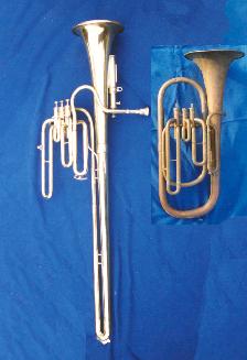
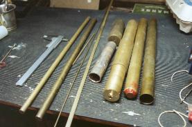
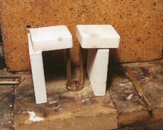
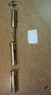
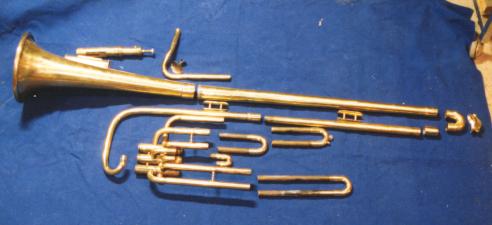
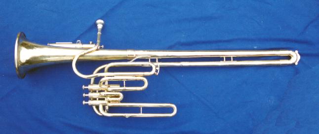
Finally, a look at what was, and what should be put together in a trick photo. They are to a
mutual scale, the "new" instrument to the left is the sudrophone with a length of 1 meter.
|
|
|
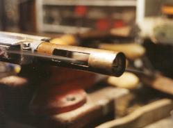
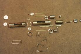
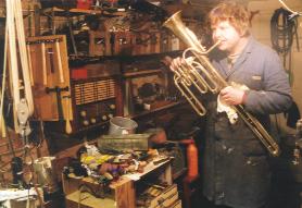
| Drawings being made. | The donor instrument. | Disassembly of the instrument |
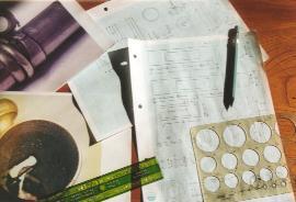
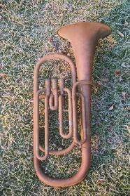
An old tenor horn had been stored in my workshop for decades, without any plans for restoration. It was found well suited for this project, and thus disassembled. The drawings were adjusted to fit the given measures of this instrument.
|
|
|
| Raw brass parts for the membrane valve | Marking out the items | First machining |
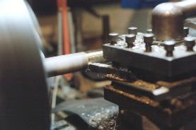
Being the most complex part, the membrane valve was built first. Raw brass parts were found from the store, and marked out with the required sizes for the valve.
|
|
|
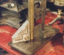
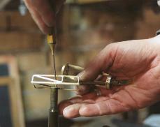
| Frame for the membrane valve soundhole | Threads made on the adjustment screw | The begin of the membrane frame |
The membrane valve consists of many small parts, here some of the parts are seen in manufacture. The frame for the membrane soundhole is made from 4 parts, soldered together with brass-tainted silver. The membrane tension can be adjusted with a screw. The thread of this screw is fine to allow comfortabe adjustment. The membrane beats towards a skeleton that also keeps the membrane in shape. That skeleton was made form 2 mm brass wire.
|
|
|
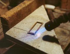
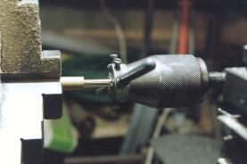
| Last finish for the membrane skeleton | A quite precise soldering process at the membrane base |
The valve cylinder in progress |
The membrane skeleton was soldered up from 2 mm brass wire, with a central brass base for attachment to the valve mechanism. The membrane is fixed at each side of the membrane valve's soundhole, two guides must be soldered in place with a tolerance less than the membrane thickness (ca. 0,1 mm).
|
|
|
| The membrane skeleton being riveted to the membrane tension arm |
The inner valve cylinder being soldered | Trimming the outer valve cylinder to size |
The parts are being assembled now, the use on a musical instrument requires that parts are assembled with precision, or the will resonate with the vibrations of the instrument. Only the membrane is supposed to vibrate! Riveting and soldering is a good method to grant silent strong joints.
|
|
|
| All parts of the membrane valve before assembly. The membrane is not shown |
The membrane valve | The membrane in place |
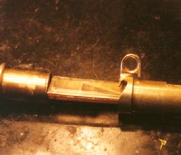
I will cut it a little short now, a last look at the many parts just for this valve, then we see it almost assembled, ready to get the membrane installed. Finally the membrane is installed.
But it is far from a sudrophone yet! This was just the small membrane valve.
|
|
|
|
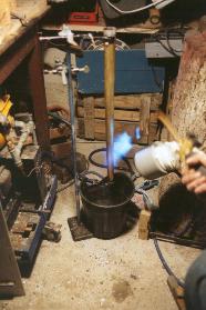
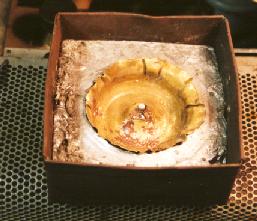
| Melted lead is | founded into the | tubes to be bent. | Bending hoes hammered down |
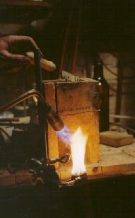
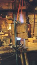
In order to use the same brass alloy for the whole instrument, the old tubes are reused. This requires straightening of the bows, and is made by casting melted lead into the tube. The tube is then straightened. Excess brass build up small hoes that must be hammered down before they get too large. Annealing before the casting is important.
|
|
|
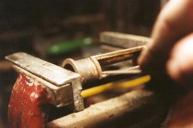
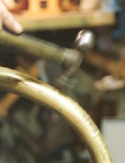
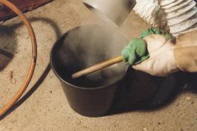
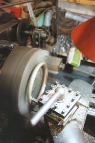
| Straightening the tube | Melting out the lead | Grinding small roughnesses |
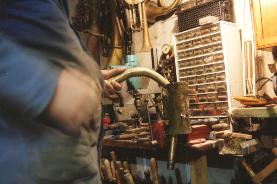
Seems complicated, but necessary. The tube is straightened with hand power, using a drilled out piece of wood as anchor. In shape, the lead is melted out and small roughnesses from the hoes and the hammering grinded away with fine emery cloth.
|
|
|
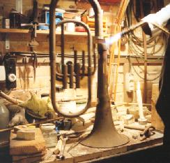
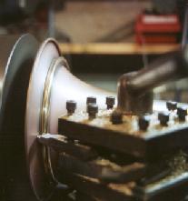
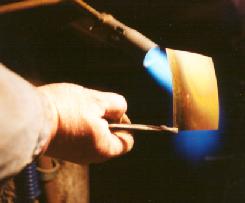
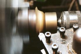
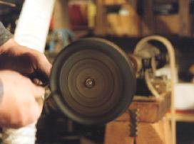
| Annealing brass garland | Bending brass | Turning garland to shape |
The original "donor" instrument had a bell with a simple rim spinned over an iron wire. This rim would not match the traditions of Sudre, his instruments had narrower bells, and a nice garland. In order to make a garland, a 12 mm brass rod was annealed with immediate shock cooling, and bent to shape and finally hard soldered to perform a ring. The ring was turned to match the bell on one side and a shape on the other side.
|
|
|
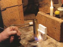
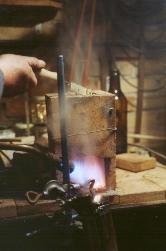
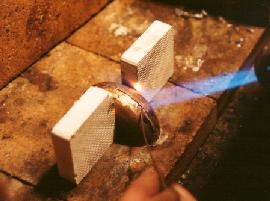
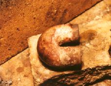
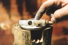
| Soldering garland to bell | Cutting off excess bell | Making hole for membrane valve |
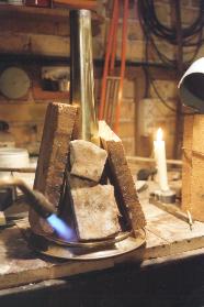
Soldering the garland to the bell requires that both parts match precise, and stay so while soldering. Temperature while (tin) soldering wil rise to 350° celcius, and the garland will expand, while the thin brass wil allow the garland to sink a little lower. Therefore the garland was kept in place with weights, here simply fireproof stones. The garland has a smaller diameter than the original bell, the excess rim and bell was cut off with a point steel, having a remarkable negative cutting angle (-20 degrees) in order to prevent damage to the bell when penetrating the thin metal. Finally a hole for the membrane valve is made. The location of the hole is not a matter of large precision, the membrane valve will work as an open key like on a keyed instrument. The narrow size of the hole, ant the fact that the passage is restricted by the membrane gives only a little tuning off that can easily be corrected with the tuning slide. Later test proved that A (220 Hz) rised to 223 Hz when the membrane valve was openend. That offset can easily be corrected with the tuning slide, or with intonation.
|
|
|
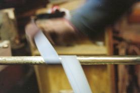
| A special tool... | Cutting off brass foil | Annealing brass foil |
At the bottom of the sudrophone a very sharp bow with a quite large inner diameter is found. Much can be found in my store, but not that one. A special tool was made in the shape of a half tube diameter, being some eccentic to maintain the bore shape. For this tool a second part was formed with lead. A suitable piece of brass was cut and annealed. It is meant to be pressed in a shape that performs the half shape of the bow, in a full circle. Cutting the circular halfpart into two halves makes a full bow... Confused?
|
|
|
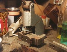
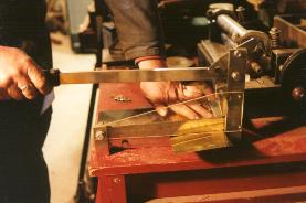
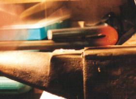
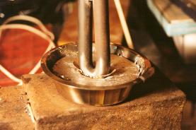
| In the press | The result | Cutting excess brass |
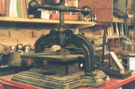
The tool pressed the annealed brass foil into perfect shape, the strange shape is seen in the open form. Excess brass was cut off using same method as with the bell.
|
|
|
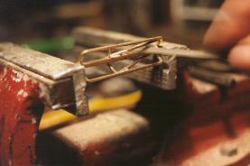
| Two halfparts | being soldered | makes this bow. |
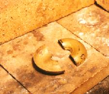
From the cut trough pressed item, two halfparts were obtained, they were woldered together to perform a bow with slight conical bore. Two smaller pieces of straight tube were added to be able to solder it to the rest of the instrument.
|
|
|
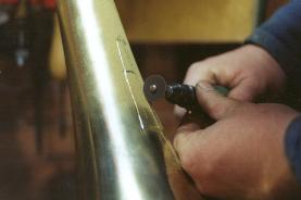
| Another tool is made | and used to make a | shield for the sharp bow. |
The sharp bow is fragile, as the brass is just 0.3 mm thick. Furthermore the bow is at risk on the long instrument when handling. A shield can help to protect, and is made of 0,5 mm brass being pressed to shape by hammering a tool made of 22 mm iron in the shape of the bow down in a plain lead surface, with the brass foil between the tool and the lead form.
|
|
|
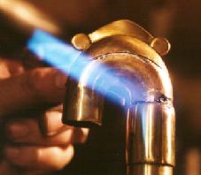
| All parts before assembly | Before soldering | Polising.. |
Fianlly all parts are redy for assembly. The instrument is asembled with iron wire before the tin soldering process begins. Solder joints are claned and polished.
|
|
|
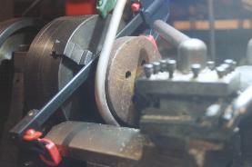
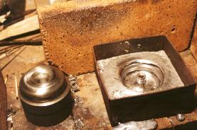
| Valve | being lapped. | Examination. |
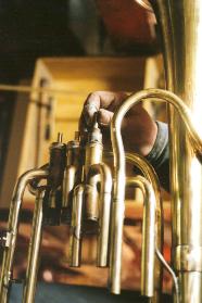
The valve engine did not require any changes for its new use, but some maintenance had to be done, valves were cleaned and one needed a little lapping. The the first attempts could be made. It proved to be tight, and in tune.
And here is a new sudrophone!
It also plays...